Press the 'Report' button to get a report that shows a load flow summary and detailed load flow results at each bus.įinally, start simulation and check that it starts in steady state. Note that the Load flow Bus block displays the bus voltage magnitude and phase angle as block annotations. Press the 'Apply' button to apply the load flow solution to the model in order to start the simulation in steady-state. The Load flow parameters are defined in the Load Flow tab of the Synchronous and Asynchronous machine blocks, Three-Phase Source block, Three-Phase Dynamic Load block, and the Three-Phase RLC Load blocks. The five Load Flow Bus blocks are used to specify the bus base voltages and to specify the voltage at PV bus and the voltage and angle of the swing bus. A 150 MW power plant using a 13.8 kV synchronous generator is connected at the 120 kV bus through a 13.8 kV/ 120 kV transformer.

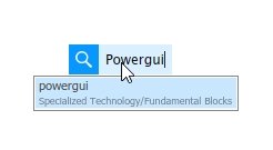
The 120 kV network is modeled by a simple inductive voltage source (short circuit power of 1200 MVA) using the Three-Phase Source block. % Magnitude and phase of frequency response.The model shows a 9 MW wind farm using asynchronous generators and exporting power to a 120 kV network through a 25-kV distribution feeder. % 500 points between decades 10^1 and 10^4. % Generate logarithmically spaced vector of frequency values. % Obtain the matrices (A,B,C,D) of the state-space model of the circuit. Since the behaviour of an RLC circuit varies depending on the frequency, I used the bode function to obtain the magnitude and phase of the admittance for the range of frequency values spanning from 10 Hz to 10 kHz. Then I named the model as my_rlc and saved it in my working directory.įinally, I created the following script (inspired by this example) which makes use of the power_analyze function to obtain the state-space model of the circuit ( my_rlc) from which the admittance can be obtained. Since you did not provide any particular values for the circuit components, I am using the defaults. This is an approach without using the Impedance Measurement block:įirst I created a simulink model of an RLC circuit using the following blocks from the Simscape Power Systems Specialized Technology Fundamental Blocks Library ( powerlib):Īside from the AC Voltage Source block and the Series RLC Branch block, the Current Measurement block and the Powergui block are necessary for the model to work. Help you and you will get better answers.

Working things out by your own means (use the documentation), and if you don't succeed, then post a Before posting on Stack Overflow you should try To work around this issue, open the library window by right-clicking on SimPowerSystems and choosing 'Open the SimPowerSystems library,' or by typing. First of all I would like to reaffirm what Ander Biguri has suggested We have verified that there is a bug in SimPowerSystems 4.0 (R14SP1) that prevents the PowerGUI from being visible in the Simulink Library Browser.


 0 kommentar(er)
